KIT - Karlsruhe Institute of Technology image/svg+xml
Institute for Photon Science and Synchrotron Radiation
  • skip navigation
  • Home
  • Legals
  • Privacy Policy
  • Sitemap
  • KIT
    • IPS Home
    • Research
      • Research
      Research
      • Materials and Processes for Energy Technologies
      • Nanostructures, Materials & Devices for Information Technologies
      • Materials & Processes for Transport Technologies
      • Imaging Technologies for Life Science and Materials Research
      • Collaboration & Innovation
    • Methods & Facilities
      • Methods & Facilities
      Methods & Facilities
      • IMAGING Cluster
      • SCATTERING Cluster
      • SPECTROSCOPY Cluster
    • News
    • Publications
    • People
    • KIT Light Source
    • Contact
    • Jobs
    • Startpage
    • Home
    • Legals
    • Privacy Policy
    • Sitemap
    Institute for Photon Science and Synchrotron Radiation


    • Startpage
    • Methods & Facilities
    • IMAGING Cluster


    • Startseite
      • IPS Home
      • Research
      • Methods & Facilities
      • News
      • Publications
      • People
      • KIT Light Source
      • Contact
      • Jobs
    • Methods & Facilities
      • IMAGING Cluster
      • SCATTERING Cluster
      • SPECTROSCOPY Cluster
    • IMAGING Cluster
    • Topo-Tomo
    • Layout
    • Methods
    • Characteristics
    • Contact

    Topo-Tomo Beamline

    The TOPO-TOMO beamline, designed and constructed with the support of the Crystallographic Institute of the University of Freiburg, provides optimal conditions for white-beam Laue topography. A large distance of 30 m between the X-ray source and the sample position as well as the possibility to reduce the effective source size by a pair of slits near the source ensure good transverse coherence, i.e., high angular resolution.

    Synchrotron X-ray topography delivers a detailed map of the distribution/structure of lattice defects and strains in crystalline samples (dislocations, micropipes, stacking faults), for example in new materials or microelectronic components. Laue X-ray topography provides:
    • large area sample mapping giving a full image of strain/defect topography of the sample;
    • cross-sectional slice images through the sample (in a manner analogous to TEM);
    • 3D directionality of crystal defects;
    • fine lateral resolution (<1μm) over large areas.


    Microtomography and microradiography allows, in a non-destructive manner, to image the internal structure of an object. Microtomography using synchrotron light sources delivers three-dimensional (3D) images of the object with high resolutions down to the submicrometer range, an excellent signal-to-noise ratio and additional contrast modes like phase contrast and holotomography. Typical applications for microtomography and microradiography are:

    • detection of voids and pores in industrial components;
    • imaging tissue and other soft materials in biological and life science;
    • pore formation in metal foams, evolution of particle coarsening in materials science;
    • crack propagation;
    • diffusion processes in woven materials;
    • characterization of fibre structures, porous media, particle agglomerations by microtomography and a subsequent 3D image analysis.


     

    Instrumental Characteristics

    Setup

    instrumentation TopoTomo

    Good coherence conditions and low background is realized by aperture slits in the front end, 25 m away from the sample. A polished Be-window close to the experiment is the only X-ray optical element in the beamline. A set of in-vacuum filters on two independent sliders can be used to change the spectral distribution of the white beam. 


    Monochromator


    A Double-Multilayer Monochromator DMM with two independent stripes - Si/W and Si/P4B on Si substrate - isinstalled. With monochromatic radiation, quantitative absorption and phase contrast imaging can be exploited, being sensitive to material and atomic numbers and to the local electron density.

    Tables


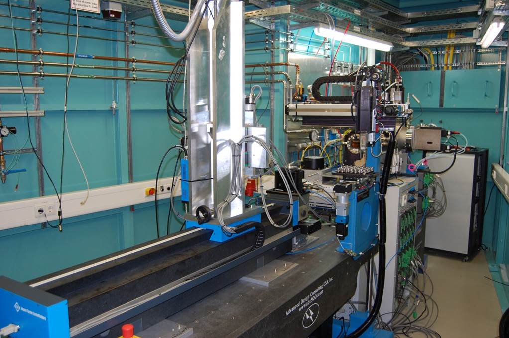
    Two motorized tables are installed in the beamline, each one dedicated to a specific class of experiments, so that switching between experimental geometries can be done by simple exchange of the optical tables, which minimizes the required time for set up.

    • The TOPO table is dedicated for experiments with white-beam topography and grating interferometry. Equipped with a positioning tower from miCos it allows mapping of large Si wafers with a diameter of 450 mm by white-beam topography. Furthermore, due to high resolution X-ray slits a large beam up to a horizontal dimension of 80 mm is available, which is especially suitable for section topography.
       
    • The TOMO table, a fast white-beam tomographic imaging station, allows tomographic scans based on radiographic projection images with spatial resolution up to 2.5 µm (“microscope”) or large field of view (5 mm x 15 mm, limited by the beam size) and moderate spatial resolution in the order of 10 µm (“macroscope”). The setup is equipped with a robot for fast sample exchange eliminating the necessity of entering the experimental hutch for switching between samples.


    Topographic setup mit Wafermapper

    Detectors


    The detectors are an essential part for high resolution X-ray imaging. Therefore, the detector pool at TOPO-TOMO was upgraded to provide a variety of detector systems suitable for different applications. Detector optics are available both for white and monochromatic beam, ranging from total magnification of 1x to 50x. Depending on the experimental requirements, the detector can be chosen for high sensitivity or high speed.

    Available methods

    White beam X-ray topography:
    Detailed information on defect distributions in crystals can be provided by synchrotron X-ray topography in which an intense, highly collimated beam of X-rays is directed onto a crystalline sample in Laue or Bragg configuration. This non-destructive analysis technique is mainly used for the study of dislocations, planar defects, stacking faults, growth defects or large precipitates. Also very small local defects like nm-scale voids in Si can be imaged as well as long range strain in electronic devices.

    High-resolution synchrotron radiography and microtomography
    High-resolution and phase contrast radiography are used to investigate micro-structured, multi-component material systems, e.g. to detect delaminations between substrates and glob tops encapsulating wire-bonded devices. Radiographs taken from different projection angles allow to obtain 3D information with a spatial resolution down to the sub-micrometer range by means of computed microtomography. The subsequent application of 3D image analysis methods can be used for the determination of size distributions, orientations or spatial correlations within the tomographic multi-constituent volume images.

    Phase contrast imaging with a grating interferometer:
    Phase contrast imaging with a grating interferometer provides determination of the refractive index distribution within a sample even for materials with similar refractive indices. The TOPO-TOMO whitebeam station enables high phase sensitivity and spatial resolution of about 5 μm together with a short exposure time below 1 s. By combining a grating interferometer with computed tomography, the refractive index distribution can be acquired in a 3D volume.


    Topo Tomo
    Topography set-up at Topo-Tomo: Mirror heater for high temperature in-situ experiments
    Topographic in situ experiment

    (1) Mirror shell and lamp housing

    (2) Window for diffracted beam

    (3) Translation/ rotation

    (4) CCD camera system

    (5) Shutter

    (6) Vacuum slits

    Important! Currently only topography measurements are available for external user groups.

    Energy range
    6 keV - 40 keV
    Energy resolution [ΔE/E]
    white light and optional 2 % bandwidth
    Source
    1.5 T Bending magnet (EC = 6.2 keV), 2 mrad horizontal, 0.5 mrad vertical
    Source size
    800 µm x 200 µm (FWHM, horizontal x vertical), can be reduced to 5µm x 5µm with slits
    Distance source - sample 30 m
    Optics Primary slits (in the front end, 5 m from the source),
    Secondary slits (26.5 m from the source)
    Be window, 0.25 mm thick, polished (27.5 m from source)
    Monochromator Double-Multilayer Monochromator (DMM) providing a monochromatic beam with a bandwidth of approx. 2% over an energy range from 6 keV to 40 keV (peak flux 1011 ph/s/mm2 @ 200 mA ring current, between 10 and 20 keV). Adjustable beam offset.
    Attenuators Filter stage 1: Al 1mm; Al 0.2 mm; Be 0.6 mm
    Filter stage 2: Cu 0.05 mm; Al 0.5 mm; Be 0.2 mm
    Flux at sample position
    ~1x10¹⁶ ph/s (10mm x 10mm), white beam
    Beam size at sample
    up to 80 mm (horizontal) x 6 mm (vertical)
    Sample environment
    Inert gas, air
    Detectors

    Photographic films (sub-μm resolution, field of view: approx. 15 x 20 cm²),
    Scintillator, coupled via microscope optics to a CCD (high dynamic range, PCO4000, 9 μm pixel size, or FReLoN 2k14bit, 14 μm pixel size) or CMOS (fast imaging, Photron SA-1, 20 μm pixel size), two optics available: macroscope (1.4x, 3.6x) and microscope (3x, 5x, 10x, 25x, 50x).


    Typical working parameters are:
    25 x 17 mm2 field of view at a pixel size of 6.4 μm (PCO + macroscope M = 1.5x);
    10 x 7 mm2 field of view at a pixel size of 2.5 μm (PCO + microscope M = 3x);
    1.4 x 0.9 mm2 field of view at a pixel size of 0.35 μm (PCO + microscope M = 25x).

    Software
    Instrument control: SPEC / PCO CamWare / TANGO camera server
    Topography data analysis: Orient-Express
    Tomography data visualization: VG Studio Max, Amira, AVS Express, Avizo, CINEMA 4D & Deep Exploration
    Image processing: IDL, MatLab, Octave
    Image analysis: MAVI, ImageJ,
    Tomographic reconstruction: PyHST, Octopus


    Team Topo-Tomo
    name function e-mail
    Cecilia, Angelica Deputy Head of Department, Beamline Scientist angelica cecilia ∂does-not-exist.kit edu
    Zuber, Marcus Head of CL/CT-Laboratory setup marcus zuber ∂does-not-exist.kit edu
    last change: 2025-01-31
    KIT – The Research University in the Helmholtz Association
    • Home
    • Legals
    • Privacy Policy
    • Sitemap
    • KIT